After uprigthing of the rig in September 1983, FALK International's president mr. Ole C. Ostlund was for some time engaged as technical advisor to a group of relatives called "The Kielland-foundation". After inspection onboard the rig on October 13th. 1983 and following examination of collected technical reports including the Statoil reports mr. Ostlund recommended further investigations to take place, particular related to the D4 upper breaking point. This request was not supported by the Commission who in public stated nothing more was to be found - "the cause of the disaster was the fatigue crack in bracing D6" - case closed.
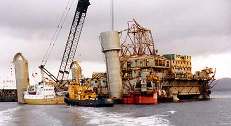
Photo 2.1.1: Alexander L.Kielland
upprighted in Gandsfjorden outside Stavanger, Oct. 1983.
The only steel material left of the D4 upper breaking point was the remaining
part attached to the uprighted rig. The intermediate piece as pictured
in the Statoil report was melted down and no longer existing. In order
to save time before the rig was sunk in the Nedstrandsfjord on 700 m waterdepth,
mr Ostlund advised The Kielland-foundation to file an official complain
to the Stavanger State Attorny. In subsequent agreement with representatives
from the French builder of the rig allowance was obtained from Norwegian
Authorities to cut off and secure the piece of the D4 bracing attached
to the rig. The cut-off piece was shipped to France, however, mr. Ostlund
and the Kielland-foundation secured samples for examination.
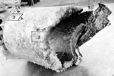
Photo 2.1.2: Bracing D4 cut-off piece
on dockside outside Stavanger.
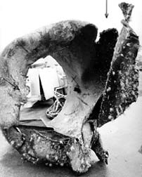
Photo 2.1.3: Bracing D4 cut-off piece.
The samples secured consisted of one "major test piece" from
the circumference of the breaking point, one "reference piece"
cut out for hook attachment during cut-off operation, one tvisted fragment
-"Spiral" and one roundish piece - "Rondell". The "major
test piece" and the "reference piece" were metallurgical
examined by Institute of Physics at the University in Oslo in late 1983
and early 1984. Their reported findings supported that an explosion likely
had taken place at the upper breaking point of bracing D4, but their interpretation
was not distinct. For information see.......
2.2 Metallografic tests of steel sample from bracing
D4 cut-off piece performed by the Institute of Physics at University
of Oslo, Norway.
In 1986 mr. Ostlund, on his own behalf, engaged Sintef
to perform examination of the "Spiral" and the "Rondell".
2.3 Metallografic and chemical testing of steel samples,
"Spiral" and "Rondell", from bracing D4 performed by
Sintef in Trondheim, Norway 1986.
Chemical testing of the epoxy coating inside the "Spiral" performed
at Sintef Division of Applied Chemistry under a separate contract showed
a carbon content in the destructed epoxy of 20 - 30 %.
Discussion:
1. Bainitt was found in all samples from the "Major test piece", photo 2.2.3. Bainitt was not found in the "Reference piece" nor in the "Spiral". Bainitt is not mentioned in the Statoil material reports. Bainitt should neither occur in the basic material. As such we can eliminate the possibility of the bainitt comming into the material at the steel mill. The "Spiral" is from the same plate as the "Major test piece" some distance apart on the circumference of the breaking point.
The literature study included in the Sintef report indicates that a shock loading of 60Gpa (600 tonn/cm2) would adiabaticly bring the temperature up to 735 degrees C. Bainitt is created with temperature above 880 degrees C and relativly rapid cooling. An adiabatic temperature rise to above 880 degrees C would require a shock loading of more than 60Gpa i.e. more than 600 tonn/cm2 may be 7 - 800 tonn/cm2 or even more? The bainitt in the "master test piece" proves that this part of the D4 bracing has been exposed to forces of this magnitude. What forces at sea could possibly create such an explosive loading?
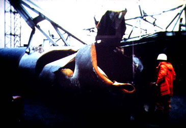
2. How come the deformation and temperature build up in the "Spiral"? The released heating from an explosion is likely rapidly exchanged with the surroundings with the burst of the bracing. The bracing is comparable with a pipe closed in both ends. After explosion in a closed pipe follows implosion. Firstly the underpressure, created by the explosion dragging the air out of the bracing, spreads down the pipe and makes the bracing collapse, sucked in, at a distance from the D-leg where inside underpressure and outside waterpressure are above material carrying capacity. The created underpressure also sucks in the weakened material at the breaking point as shown on the Statoil photos of the D4 breaking point and on the photos of the D4 "cut-off piece". Following the implosion air is sucked back, flows back into the bracing in order to equalize air pressure back to atmosphere. The air flowing back into the pipe creates frictional force and corresponding temperature rise into the material. The air tears of the outside epoxy as shown by the corroded material at slashes and breaking point on photo 2.1.4. The back streaming air twists the "Spiral", tears of the outside epoxy and by force and friction-heating deforms the fractured surface (B) of the "Spiral" developing gradually the typical strong sheerzone and smoothening the surface. The friction heat spreads through the material and carbonizes the inside epoxy of the "Spiral".
Photo 2.1.4; Bracing D4 exploded.
Conclussions:
The combined findings gives evidence of an explosion inside the upper part of the D4 bracing. This also explains the twins, the violent deformation of the bracing shown on the photos and missing material at D4 upper breaking point.
Consultation by mr. Ostlund with experts at Institute of Aeronautics at California Technical University in Los Angeles in fall 1986, outruled the possibility of focusing weak shock waves causing the bracing to collapse, leaving only the possibility of explosive force by applied explosives.
The positioning of the explosive has most likely been at or close to the "Master test piece". This follows by the bainitt in the "Master test piece" and not in the "Spiral". The position is logic as the "Master test piece" is from the lower wall of the bracing, ref photo 2.1.2 and 2.1.3. The explosive has probably been attached to, laying on to the inside wall of the bracing at this position. The orientation of the D4 "cut-off piece" is determined by the square hole (reference piece) for the fixing of the lifting hook on top side of the bracing during cut-off operation after uprighting the rig (ref. photo 2.2.1 under section 2.2).