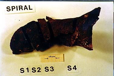
Photo 2.3.8; Spiral divided into sections.
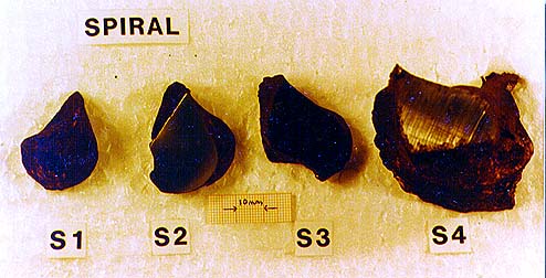
Photo 2.3.9; Spiral test samples.
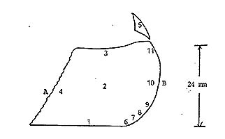
Fig: 2.3.3.
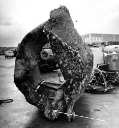
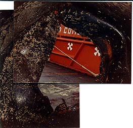
The two steel pieces tested at Sintef in Trondheim in
1986 were collected during inspection of bracing D4 "cut-off piece"
on dockside at Randaberg outside Stavanger. Both pieces were found inside
the cut-off piece, corned in at the lower side at the deformed breaking
area, covered with cuttings from the cut-off operation. Due to the sucked
in shape of the breaking area the pieces had not been allowed to escape
during capsizing and later uprighting of the rig as shown on photo 2.3.1
and 2.3.2 (see also previous photos 2.1.2, 2.1.3 and 2.2.2). Detail of
the great amount of distortion on the circumference is shown on photo 2.3.3.
The D4 bracing is 2.2 meter in diameter with wall thickness of 24mm. The
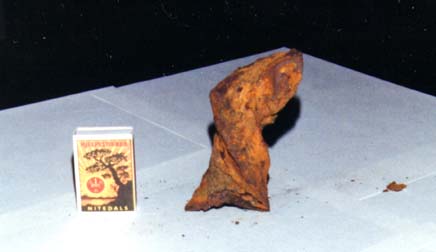
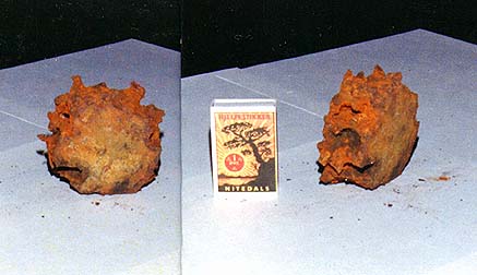
shape of the two test pieces "Spiral" and "Rondell"
are shown on photo 2.3.4 and photo 2.3.5.
Photo 2.3.1; Bracing D4 cut-off piece.
Photo 2.3.2; Bracing D4 cut-off piece from inside
towards the fractured opening.
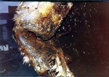
Photo 2.3.3; Detail of bracing D4 cut-off piece distorted,
sucked in, circumference.
Photo 2.3.4; The D4 "Spiral" test piece.
Photo 2.3.5; The D4 "Rondell" test piece.
The "Spiral" is a fracture from the pipe wall greatly distorted,
tvisted approximately 360 degrees. The epoxy coating on one side is gone
and on the other curved in side highly destructed. How these damages have
occured will be discussed separately. The "Rondell" is a part
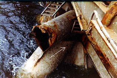
of the pipe wall. During inspection onboard the rig on Oct. 13th 1983 a
hole in The D4 bracing close to node 4 was discovered. Their shall be no
hole in this highly stressed area on the rig. A hole was observed by underwater
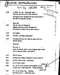
survey one month after the disaster as recorded in the log from Bloms Oppmåling
A/S on April 28th 1980. Only one hole has been located on the part of the
D4 bracing connected to the rig. This will be discussed further separately.
Photo 2.3.6; Hole in bracing D4.
Fig. 2.3.1; Bloms Oppmåling under water survey
log of April 28th 1980.
Fig 2.3.2; Bloms Oppmåling log enlargement.
In April 1986 mr. Ostlund placed an order with department
of Metallurgy at Sintef (The Foundation for Scientic and Industrial Research
at the Norwegian Institute of Technology ) in Trondheim for metallographical
testing of the "Spiral" and "Rondell" steel pieces.
Sintef presented their findings in a report dated Dec. 13th 1986.
Ref: Sintef report no. STF34 A86122 "Metallografisk og kjemisk undersøkelse
av stålprøver".
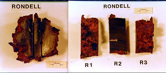
Test samples from the "Spiral" and the "Rondell" were chemical tested for material property purpose and compared to material from bracing D6 as reference. The "Spiral" was conform with D6. The "Rondell" deviated on carbon and vanadium compared to D6 but corresponded with test samples from D3 taken at the node close to the D-leg. This substantiates that the "Rondell" comes from a part of bracing D4 at node 4. Steel quality at the nodes differed from rest of the bracings for strength and welding purposes. Samples of the "Rondell" and "Spiral" are shown on photo 2.3.7 and photos 2.3.8 and 2.3.9.. One of the steel samples from the "Spiral" was examined metallografic with reference to testpoints outlined in fig. 2.3.3.
Photo 2.3.7; Rondell divided into
samples.
Photo 2.3.8; Spiral divided into sections.
Photo 2.3.9; Spiral test samples.
Fig: 2.3.3.
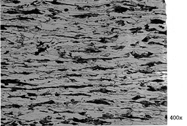
Fig 2.3.3 showns a section of the "Spiral" with testpoints 1 -11, from were micrographics are presented. Numbers 1 and 3 represents the outer and inner side of the sample. Letters A and B are ruptures. The surface at A is characterized by fibres while surface B is rounded and smooth. The numbers of the following micro(graphics) corresponds to the numbers on fig. 2.2.3. Where more than one micrographic is included they are numbered a,b,c..The micros are arranged in order to show the gradually buildup of the strong sheerzone characterizing the highly deformed B surface.
Micro 2a; No visual sign of deformation.
Micro 2b; Lower right corner of 2a enlarged.
Micro 3; Slightly deformed.
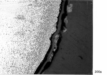
Micro 4; Fracture A, great amount of deformation.
Micro 1; Slightly deformed material.
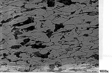
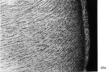
Micro 6; Moderate deformation.
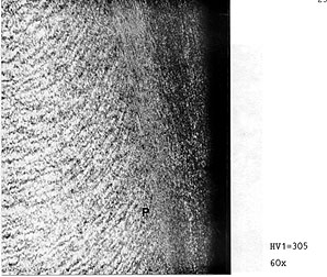
Micro 7; Starting sheerzone with subcorn.
Micro 8; Sheerzone developes inside breaking zone.
Micro 9; Sheerzone with subcorn fully developed.
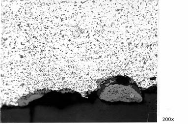
Micro 10a; Typical for the deformation of surface
B, strong sheerzone.
Micro 10b; The sheerzone is approx. 90 degrees to rolling
direction.
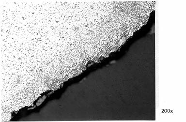
Micro 11; Very high deformation. Picture taken inside
the sheerzone.
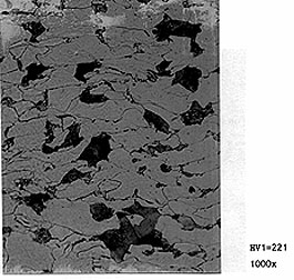
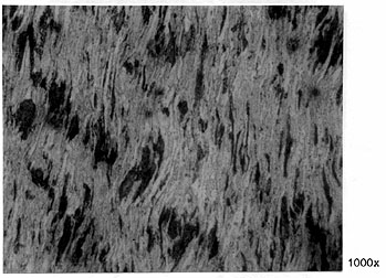
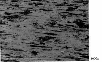
Micro 5a; Very highly deformed. Enlargement 1000x.
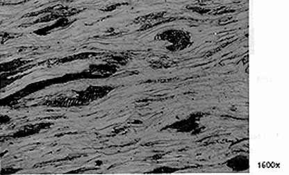
Micro 5b; Very highly deformed. Enlargement 1600x.
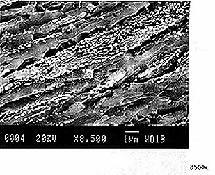
Micro 5c; SEM picture. Enlargement 8500x.
The development of subcorn at surface B indicates that the temperature
in the steel material in this area has been in the magnitude of 400 - 500
degrees C. The deformation in rest of the material is a lot less.
Sintef made a literature study in regard to shock loading
on steel material. Literature refered to in their report are:
* J.Mescall and V.Weiss, "Material Behavior Under
High Stress and Ultrahigh Loading Rates", Plenum Press, New
York, 1983 page 101-118.
* M. A. Meyers and L. E. Murr, "Shock Waves and High-Strain-Rate
Phenomena in Metals", Plenum Press, New York,
1981, specificly pages 285-298, 610, 663-666, 1041-1042.
The result of this study is taken into account under section Discussion, page 8 in the Sintef report. (Mr. L.E.Murr reveals in chapter 37 of his book the results of a large number of shock loading experiments. Shock deformation and especially explosive shock loading where a flyer plate is impacted upon a target material.) A shock loading of 60Gpa (600 tonn/cm2) on the type of steel as in Alexander L. Kielland, will locally increase the material temperature to 735 degrees C while the shock wave passes through the material and thereafter drop to 396 degrees C. This due to adiabatic heating. Such temperature increase creates structural changes in the material.
Summary: Sintef gives in their report no distinct explanation of the gradually developed sheerzone nor the temperature buildup to 400-500degrees C at surface B. No bainitt was found in the steel material.