2.0 ASSEMBLY OF BRACING PARTS.
The headquarter of the Norwegian state owned oil company
STATOIL in Stavanger was engaged to assist the Commission with material
and fracture investigations. Material from the broken away D-leg, underwater
surveys of the capsized rig and parts of the 6 broken bracings connecting
the D-leg to the rest of the platform were made available to Statoil. The
results were presented by Statoil in two separate reports given to the
commission. The reports includes assembly of bracings and photos of fractures.
Information given under this Section 2.0 is taken from the Statoil report
to the commission.
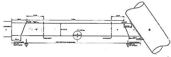
Fig.2.1: Assembly of bracing D3.
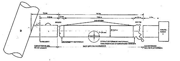
Fig. 2.2: Assembly of bracing D4.
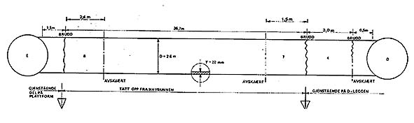
Fig.2.3: Assembly of bracing DE.
The assembly of bracing D4 as presented in fig. 2.2 shows that material
is missing. No material shall be missing as the result of a pure mechanical
failure, compare assembly of bracings D3 and DE in fig 2.1 and fig 2.3.
The documented missing material in bracing D4 calls for additional investigations.
The following photographs are reproduced from the Statoil
report to the commission:
Photo D3-1; Bracing D3, upper breaking point, below
deck.
Photo D3-2; Bracing D3, lower breaking point, at D-leg.
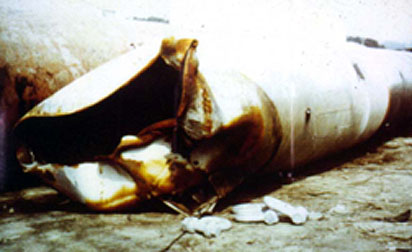
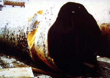
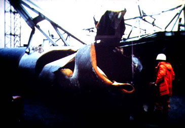
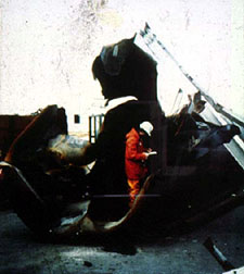
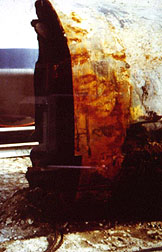
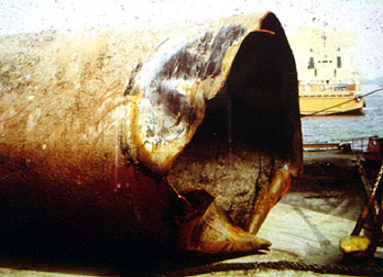
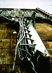
Photo D4-1; Bracing D4, upper breaking point, exploded?
Photo D4-11; Bracing D4, upper breaking point, picture
2.
Photo D4-2; Bracing D4, lower breaking point.
Photo DE-1; Bracing DE, breaking point at E-leg.
Photo DE-2; Bracing DE, breaking point at D-leg.
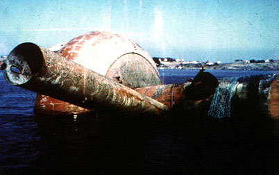
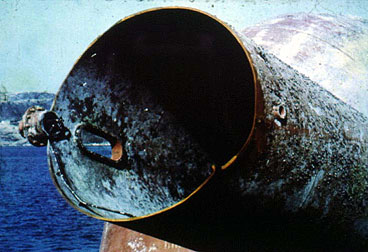
Photo D-leg; The broken away D-leg.
Photo D6; Bracing D6 with the fatigue crack.
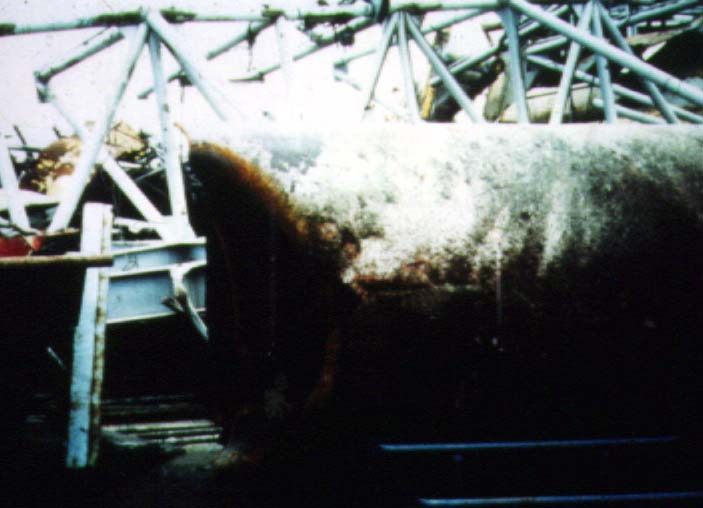
Photo D6 shows the undisputed fatigue crack in bracing D6. A major question
is, however, what caused the fatigue crack to develope into failure at
18.30 hrs on March 27th 1980? The weather conditions, wind and waves (including
anchorforces), or additional loadings due to loaddistribution caused by
failure of another part of the rig, as f.i. one of the other bracings connecting
the D-leg to the rest of the platform ?
Visual inspection of the upper breaking point of bracing
D4, photo D4-1 and photo D4-11 calls for attention. The upper D4 breaking
point is dramaticly different from the breaking points shown on the other
photos. The breaking point is violent with slashes and curved in fracture
surfaces typical for explosion in closed pipes. The length of the bracing
is about 29 meters with diameter 2.2 meter and 24 mm wall thickness.
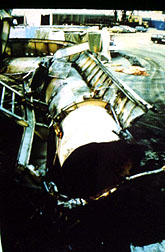
Photos D4-1, D4-11 and the missing material (fragments)
documented in fig. 2.2 gives an undoubtful indication of what caused the
D4 bracing to collapse. Load carried by bracing D4 will after its failure
have to be redistributed, i.e.taken up by the other bracings, mostly D6,
D3 and DE. Further shock waves from the explosion inside D4, and the created
seawave, will push the D-leg apart from the rest of the platform causing
the fatigue crack in D6 to fail and the breakaway of the D-leg, bracings
DE and D3. The two remaining top bracings TD3 and TD4 will be bent during
platform collapse, the deck comes down and the D-leg floats up. After some
time in the seawaves TD3 and TD4 are teared off.
Photo TD3; Bracing TD3.
Photo TD4; Bracing TD4.
Further proof and documentation of the explosion in D4
could easily be obtained by metallurgical testing and/or energy calculations.
However, as documented by the non-scratched breaking points in fig 1, material
from the explosion area in bracing D4 was never sent from Statoil in Stavanger
to Sintef (The Foundation for Scientific and Industrial Research) in Trondheim
for metallurgical testing.
Sintef concluded that the disaster was caused by the fatigue
crack in bracing D6 and the Commission stated in their official report
of May 1981 that time did not allow any investigations of other causes
to the disaster as for instance explosion, ref. Commission official report
NOU 81:11 page11.
2.1: Material testing of bracing
D4 upper breaking point.